How to Choose Floating Compensation Unit
Jul. 02, 2026
What is Floating Compensation Unit?
"Floating compensation" is not a single, universal industry term; it refers to entirely different technologies or mechanisms depending on the field. In the context of industrial automation and robotics (mechanical and control engineering), a Floating Compensation Unit refers to the ability of a robot's end-of-arm tooling (EOAT) to absorb positional and angular deviations in real time through a floating joint or module.
Floating compensation effectively resolves alignment and positioning deviations during automated assembly, significantly enhancing manufacturing flexibility. Depending on the application requirements, operators can select single-axis, dual-axis, or tri-axis floating units.
Operating Principle: It utilizes springs, pneumatic cylinders, or elastomeric components to grant the tool-side multi-directional degrees of freedom. When minor tolerances or errors exist in the workpiece position, the end-effector automatically "floats" to adjust its posture, preventing rigid collisions.
Core Function: It improves assembly precision, protects workpieces and equipment from damage, and overcomes the positioning inaccuracies inherent in rigid robotic systems.
In which fields are floating compensation units used?
Floating compensation technology is primarily applied to resolve conflicts between a robot's rigid end-effector and workpiece tolerances or positioning deviations. Its core applications are concentrated in the following scenarios:
1. Precision Assembly and Insertion
This is the most widespread application for floating compensation, specifically used to eliminate concentricity errors in hole-and-shaft mating.
Pin/Connector Insertion: During the insertion of electronic connectors and wire harness plugs, the unit automatically compensates for X/Y positional offsets and angular tilts, preventing pins from bending or breaking.
Bearing/Gear Press-Fitting: During motor rotor embedding and bearing press-fitting processes, Z-axis floating absorbs height tolerances. This ensures that force is transmitted cleanly along the central axis, preventing uneven load wear.
3C Product Assembly: Applied in tasks like mobile phone screen bonding and precision component fastening, it adapts to micron-level tolerances to significantly boost first-pass yield rates.
2. Automated Material Handling and Machine Tending
This resolves issues where parts fail to be gripped properly due to inconsistent incoming material positions, fixture wear, or conveyor belt shifting.
Machine Tool Tending: It compensates for positional fluctuations in castings and forgings caused by casting tolerances. This achieves "soft-touch" gripping, reducing jamming and downtime needed for debugging.
Flexible Gripping: Designed for thin-walled parts or components with highly polished surfaces, it absorbs posture deviations via floating cushioning to prevent scratches or stress damage caused by rigid clamping.
Pallet/Production Line Pick-and-Place: It adapts to pallet deformation or stacking offsets, ensuring reliable picking and placing under high-speed cycle times.
3. Specialized Process Machining
Provides compliance support in processes that require constant force control or adaptive path tracking.
Deburring and Grinding: It maintains a constant contact force between the tool face and the workpiece surface, adapting to complex curvature changes while preventing over-grinding or missed spots.
Projection Welding and Riveting: At the exact moment of welding or riveting, it allows the end-effector to micro-adjust its angle. This ensures the electrode or rivet remains perfectly perpendicular to the workpiece surface, improving joint quality.
Dispensing and Sealing: It compensates for path deviations to guarantee a uniform and continuous adhesive bead, preventing breaks or overflow.
4. High-Mix, Low-Volume Mixed Production
Accommodates the need for rapid changeovers in small-batch, multi-product manufacturing models.
Rapid Changeovers: Eliminates the need for reprogramming or meticulous recalibration. Through mechanical self-adaptation, it natively compatibly handles workpieces of various sizes and shapes, shortening line changeover times.
Tolerance Absorption: Automatically absorbs dimensional variations from different suppliers (typically within ±0.5mm), lowering the strict precision requirements placed on incoming raw materials.
This technology is typically integrated into robot End-of-Arm Tooling (EOAT). Through mechanical springs, pneumatic drives, or servo setups, it delivers degrees of freedom for X/Y/Z translation and Rx/Ry/Rz rotation. A typical error absorption range spans from ±0.5 mm to ±8mm, with angular compensation reaching up to ±5˚.
How to Choose Floating Compensation Unit
Now that you understand the core concepts behind the Floating Compensation Unit, let’s dive into How to Choose Floating Compensation Unit. The following guidelines feature the fouk gripper FD series Floating Compensation Unit for demonstration purposes; references to other brands of Floating Compensation Units are for comparative reference only.
introduction of fouk gripper’s Floating Compensation Unit
The fouk gripper FD series offers floating compensation across three directions: translational movement in the X and Y axes, along with rotational compliance around the Z axis. Our floating compensation unit is designed with three distinct air lines. When pressurized, it enables multi-directional floating compensation, including X/Y axis movement and Z-axis rotation (as shown in Figure 1).

When this specific air line is pressurized, the unit executes a center-locking reset. For example, regardless of its current drifted position, as soon as air flows through this port, the unit instantly centers and locks back into its baseline position (as shown in Figures 2 and 3).


There is a subsequent air line dedicated to locking the unit at any arbitrary position. If you want the floating module to stop and lock at its exact position mid-motion, pressurizing this port locks it firmly in place, preventing further movement in any direction (as shown in Figure 4).

Additionally, the unit features two magnetic switch slots designed to detect whether these air lines have pressurized successfully and whether the locking mechanisms have engaged properly.
types of fouk gripper’s Floating Compensation Unit
The FD Series features three models: 50, 63, and 80.
The XY compensation range is 2.5mm to 4mm.
The angular compensation ranges from ±12˚ to ±16˚.
The maximum recommended payload is 15kg.
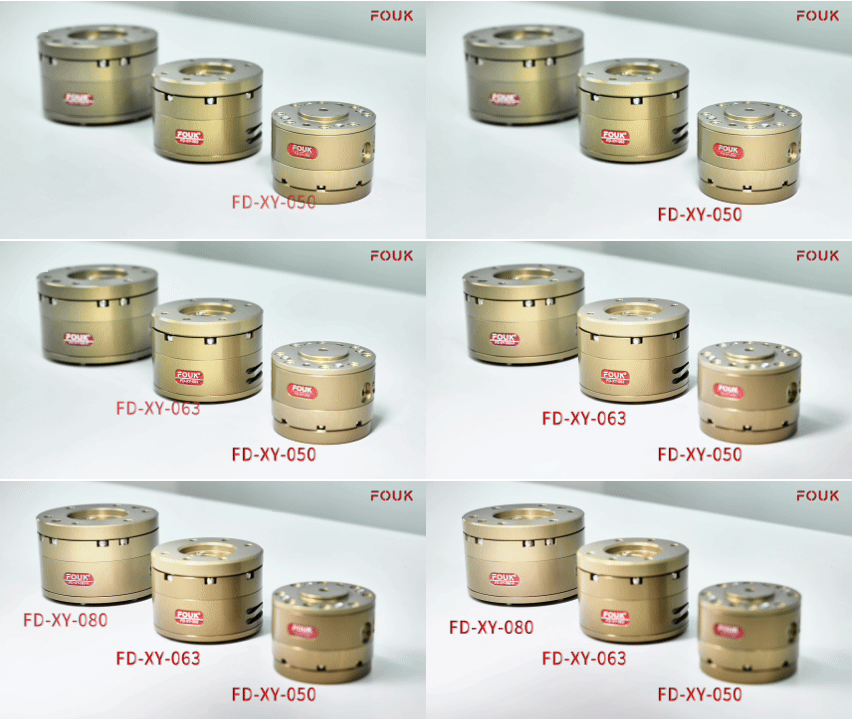
The F Series features four models: F8, F14, F20, and F24.
The XY compensation range spans from ±4mm to ±12 mm.
The Z-axis compensation ranges from 10mm to 14mm.
The maximum payload reaches up to 160kg.
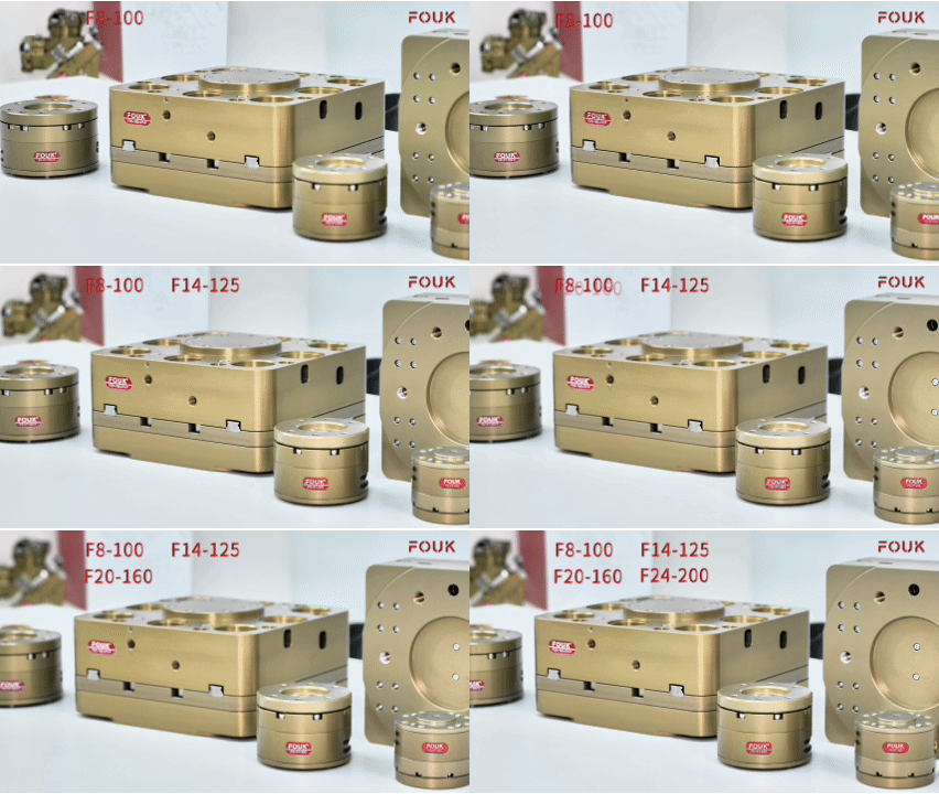
A Step-by-Step Guide to Selecting Floating Compensation Unit
How do you choose between the FD Series and the F Series? If your application requires a compact footprint and rotational movement around the Z-axis, select the FD Series. If your application demands large error absorption, heavy payloads, and long stroke lengths, select the F Series.
example of Selecting Floating Compensation Unit
Suppose we have a workpiece weighing 7kg that requires a floating compensation range of ±4mm. Based on the workpiece weight and stroke requirements, we can consult the Fouk selection catalog (shown below) and initially see that the F8 series appears to be a suitable match, as its recommended handling weight and stroke meet these baseline needs.

However, in actual application scenarios, when a collaborative robot is connected to a floating unit, it will tilt and swing the workpiece at various angles. During these maneuvers, the recommended handling weight capacity transitions from a vertical orientation to a horizontal orientation. Looking back at the chart, while the F8 series possesses sufficient vertical payload capacity, its horizontal capacity drops to 5.5kg, which fails to safely support our 7kg(as shown below). Therefore, we must step up to the F14 series. As a rule of thumb, when a workpiece moves from a vertical to a horizontal orientation, you must size up the unit model.

Let us assume we have now selected the F14 series based on the 7kg workpiece payload and the required ±4mm horizontal stroke tolerance.

Next, we must calculate and verify whether the load limits of the F14 series can truly withstand the structural forces.
Assume the distance L from the center of gravity (CoG) of the workpiece to the mounting surface of the F14 is 100mm. We must determine if the F14's torque capacity can safely handle this downward overturning moment. The simplified calculation formula is:
M = m*a*L
(Where “a” represents the combination of gravitational acceleration and mechanical acceleration. To account for extreme operating conditions, we typically apply a safety factor of “3G”.)
Therefore:

This means that under a horizontal load state, with the workpiece center of gravity located 100mm from the F14 mounting surface, the overturning moment is 21 N*m.

Referencing the catalog parameters in the diagram above, the maximum allowable torque capacity for the F14 is 55N*m. This provides a safety factor of more than 2x, meaning it comfortably satisfies our load requirements.
Alternatively, we can work backward to calculate the maximum permissible distance (L). Since the catalog lists the maximum torque (M) as 55N*m, we apply a 2x safety factor, yielding a maximum working torque of:

Plugging M and a back into the formula gives:

This tells us that if the center of gravity distance exceeds 130mm, this specific product's load capacity will be insufficient, and a larger model must be selected.
To summarize: When selecting a floating unit, never look solely at the model name or the vertical payload rating. Always remember: upsize for horizontal payloads, and always calculate backward for the overturning moment.


